Internal resistance is a critical parameter that determines lithium-ion battery power capability, energy efficiency, and heat generation. It is also an important indicator of the state of health (SoH) of the batteries, which influences the design of electric vehicle acceleration, fast charging, and cooling systems (EVs). Furthermore, the Battery Management System (BMS) must establish an internal resistance model to accurately manage the power capability to avoid battery abuse and improve battery safety and service life. As a result, research on internal resistance and power capability is critical in the development of next-generation battery cells and the optimization of battery systems. However, as a cost-cutting measure, manufacturers are increasingly adopting ultra-low DC internal resistance and enlarging single-cell designs. However, as manufacturers adopt ultra-low DC internal resistance and enlarge single cell designs to improve electric vehicle power density, general equipment is increasingly unable to deliver the required test current of thousands of amperes, leaving test engineers with a limited choice of expensive equipment.
Nowadays, battery internal resistance measurement technique is mostly separated into two types: 1) Pulse (step) current is generally utilised to measure the potential difference, which is then used to calculate the internal resistance value. 2) Electrochemical impedance spectroscopy (EIS) using disturbance spectrum technology is used to evaluate AC resistance. The battery’s complicated electrochemical characteristics prevent direct comparison of the DC resistance and AC impedance. The two measurement techniques are complementary due to the difference in the analyses’ time domains and are mostly selected according to the application conditions.
In the design of electric vehicles and energy storage systems, pulse current is frequently used to test DC internal resistance. In addition to the short test time, research has shown that current amplitude affects the internal resistance of the battery [1] and that the high-current pulse test more closely approximates real load applications. The VDA current step method [2] and the Hybrid Pulse Power Characterization (HPPC) test [3] [4] are internationally standard methods for pulse current testing, with pulse widths ranging from 100mS to 30S.
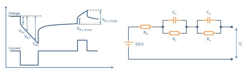
Depending on the measurement timescale, the voltage drops are influenced by various internal resistance phenomena: ohmic resistance of the transient voltage drop, equivalent capacitance and interface electric charge transfer resistance during the first few seconds of the voltage drop, and polarisation resistance of slower response due to ion diffusion (Figure 1). The total resistance is calculated using the pulse test results. It should be noted that a wider pulse width may change the state of charge (SOC) and cause additional voltage drops, resulting in internal resistance measurement deviations. A too-small pulse amplitude, on the other hand, will result in a significant increase in measurement uncertainty. Errors in current/voltage measurement and temperature control can also cause measurement errors.
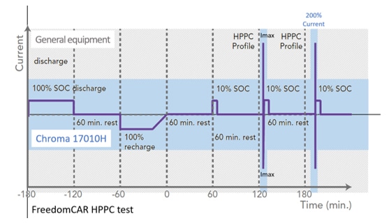
The internal resistance and power characteristics of the battery are calculated during USABC HPPC tests by subjecting battery cells to 10~30S of maximum pulse discharge and 10S of maximum pulse charge under different SOCs to measure the change in electric potential. According to this principle, if a 60Ah lithium battery cell needed to have its pulse working current (10C-rate) tested ten times, 600A charging and discharging equipment was required. But not anymore, because Chroma now offers a 200% pulse current test solution!
The Chroma 17010H has a single channel current capacity of 300A, which can be amplified with Super Mode to output 200% current (600A) in 30 seconds, making it ideal for pulse current performance testing. The new design prioritises battery applications and optimises the power output mode, resulting in a 50% smaller footprint and a 30% lower price (Figure 1).
The temperature control of the power circuit is critical to Chroma’s high pulse current capability. For starters, the 17010H’s high-conversion-efficiency energy recovery architecture significantly reduces component heating during charging and discharging. Second, by optimising power module integration and component selection, it increases operating current. Finally, a heat flow design is used to control temperature. In terms of measurement, a distributed high-precision current transformer structure ensures current accuracy, and a cold and hot area circuit layout reduces temperature drift, resulting in an integrated battery test system with a 200% pulse current output.
The following are the primary benefits of Chroma 17010H:
- High measurement reproducibility saves testers time on trend judgment and characteristic analysis.
- Zero-crossover and fast current response capabilities, test results closely resemble real-world applications.
- With a minimum current range of 1:10 and suitable ranges for both high and low-rate performance tests, the multiple current range design improves the accuracy of small currents.
- A 75% discharge energy recycling efficiency not only saves operating power and reduces waste heat from air conditioning, but also reduces laboratory power distribution requirements.
- Independent Level 2 V. Protection function improves high current testing safety.
MORE FROM THE MEDIA HUB

February 2, 2024
Future Propulsion Conference 2024
READ MORE
January 15, 2024
A dedicated resistance meter? Here is when it makes sense…
READ MORE
December 4, 2023