Category: Product News
Motor Measurement From Performance Analysis To Quality Testing
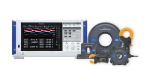
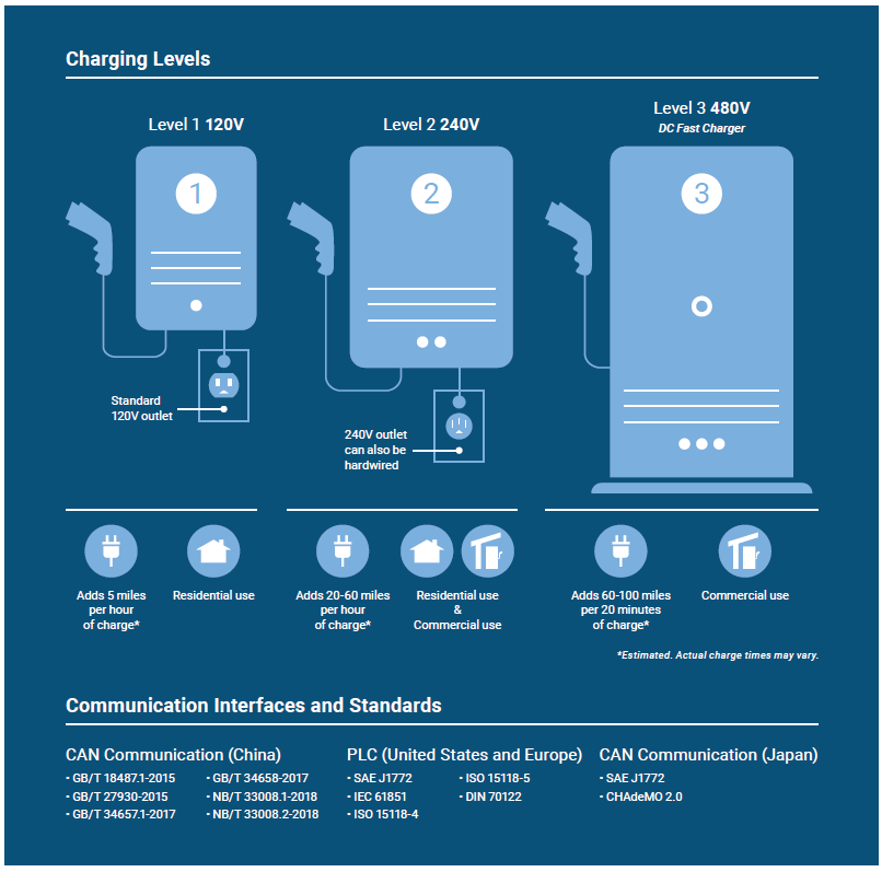
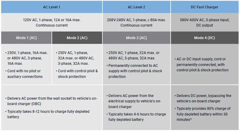
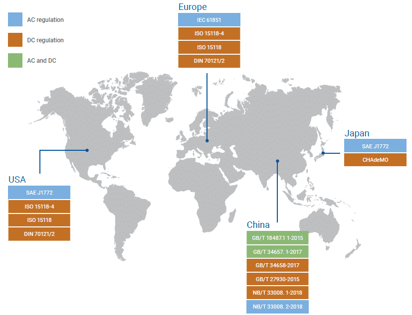
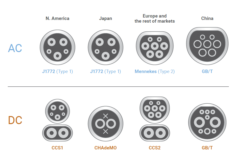
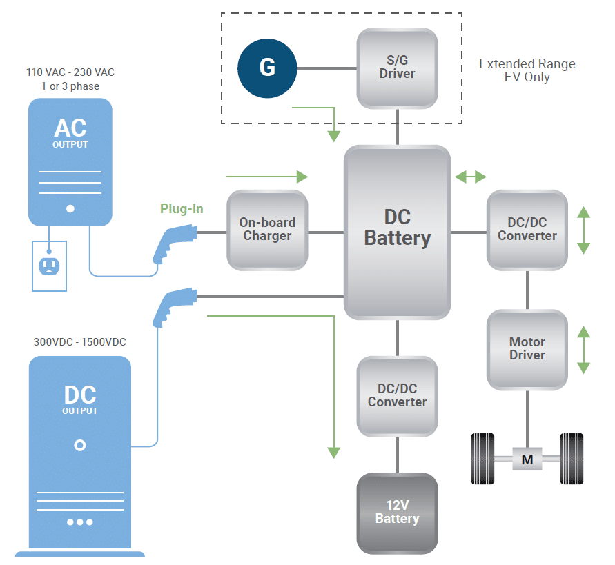
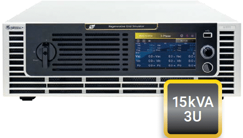
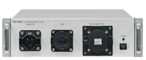
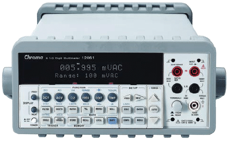
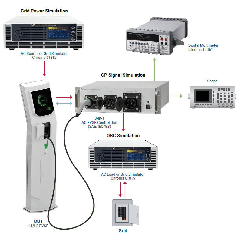
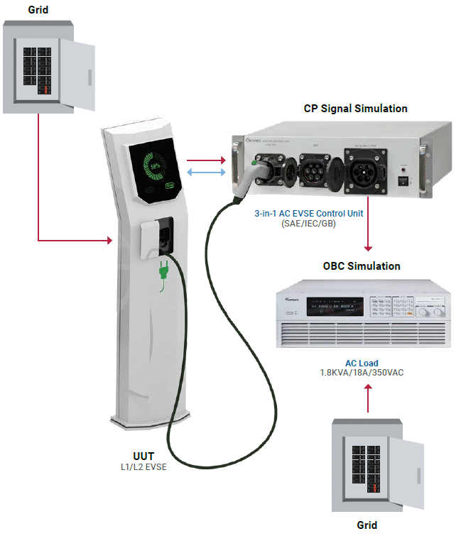
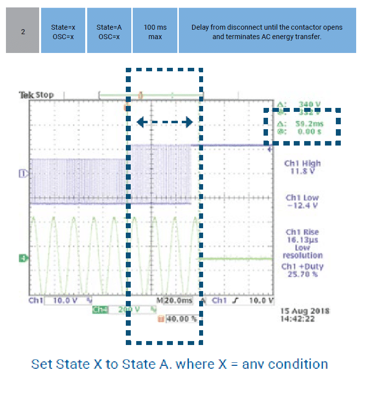
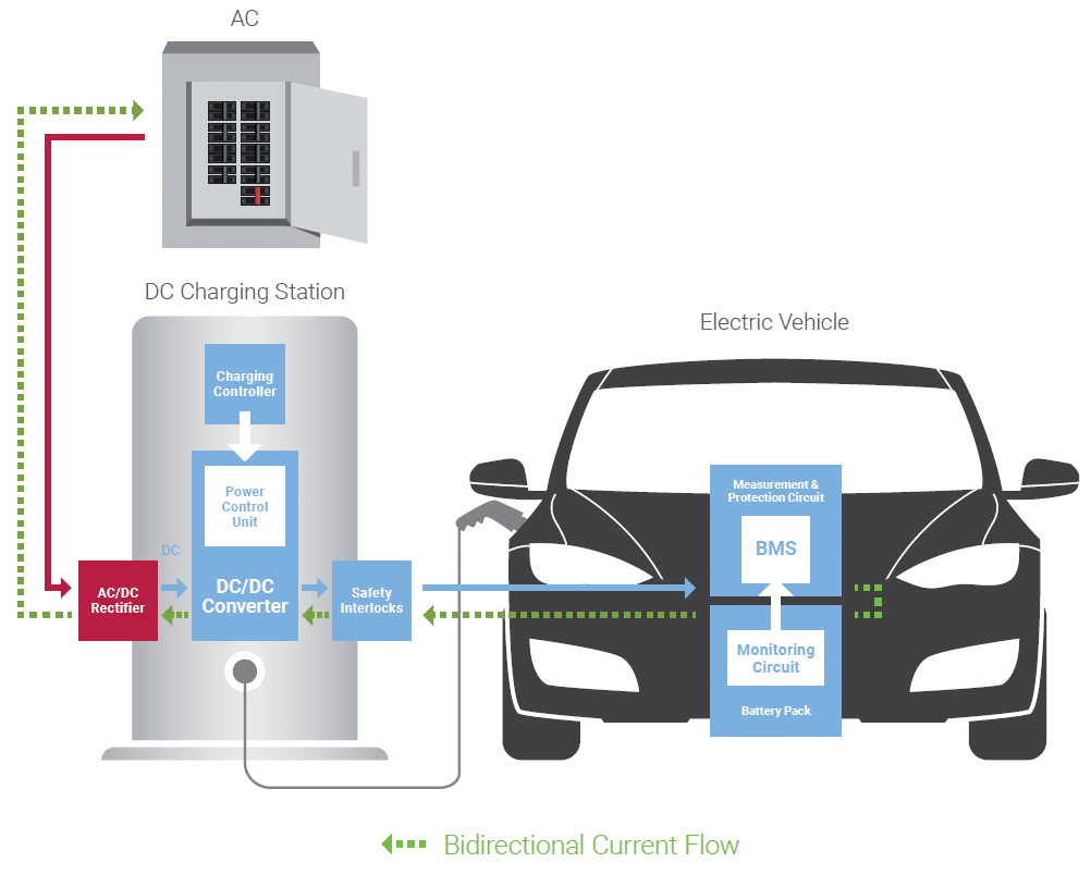
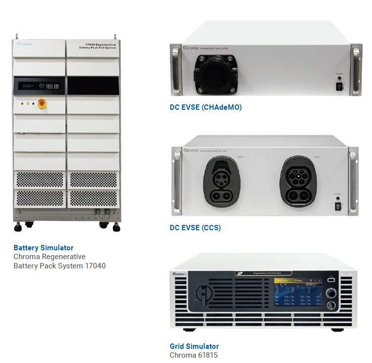
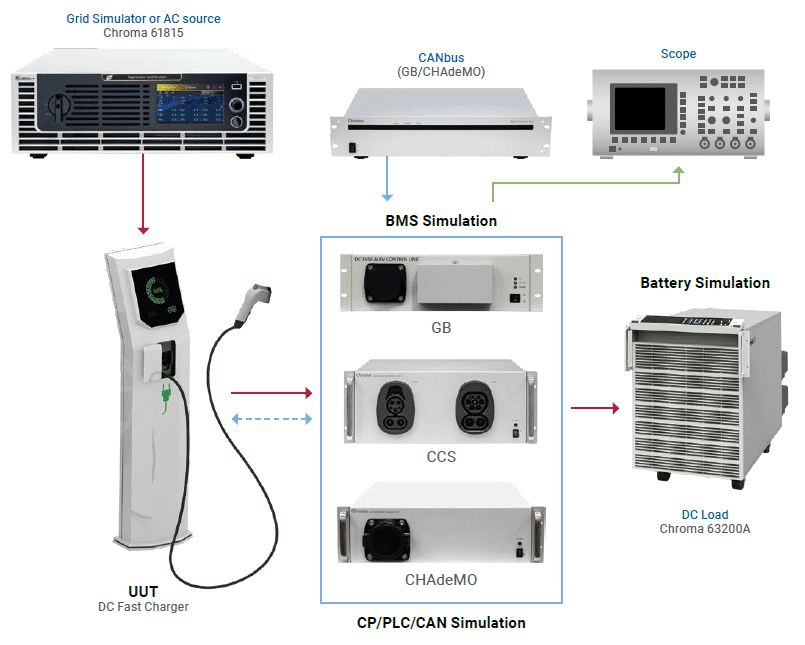
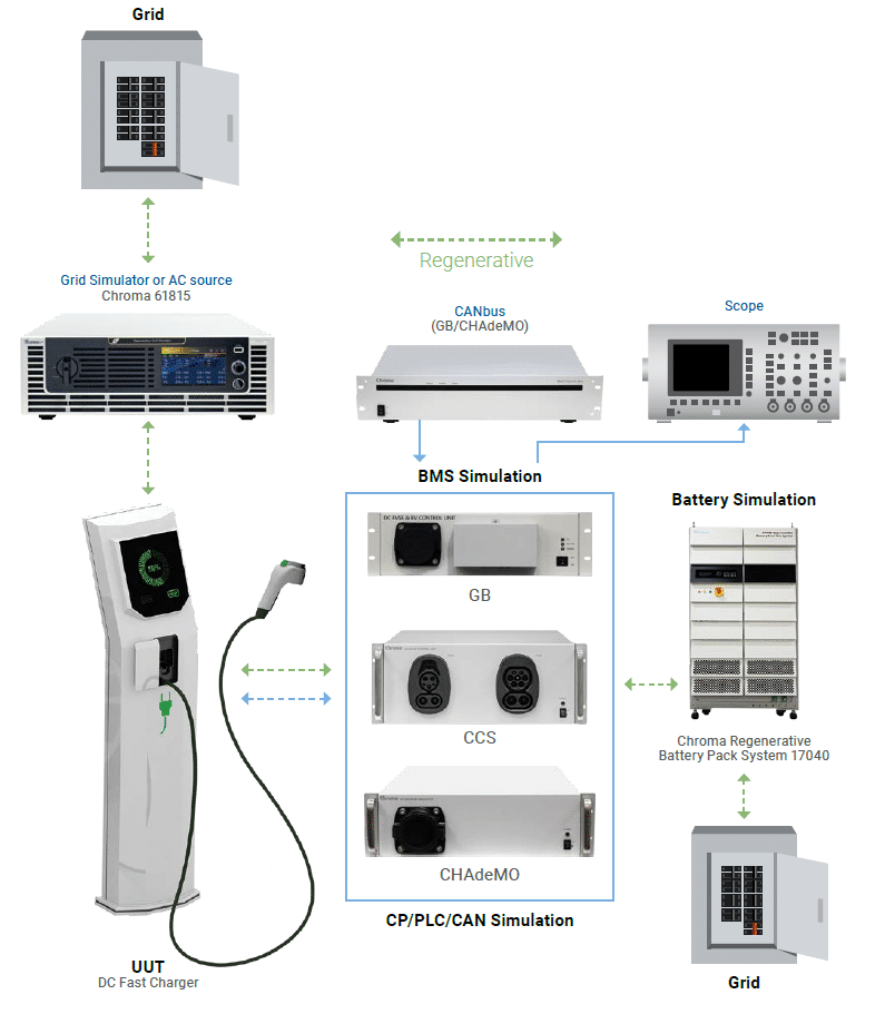
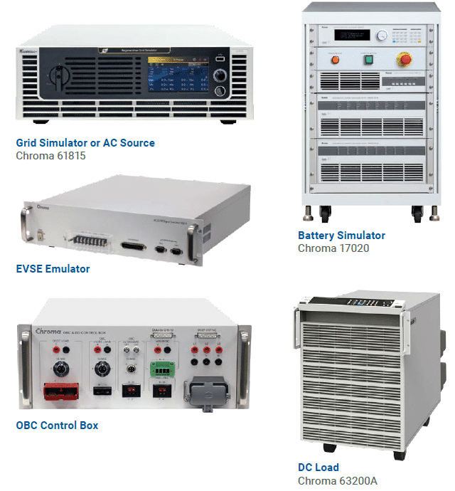
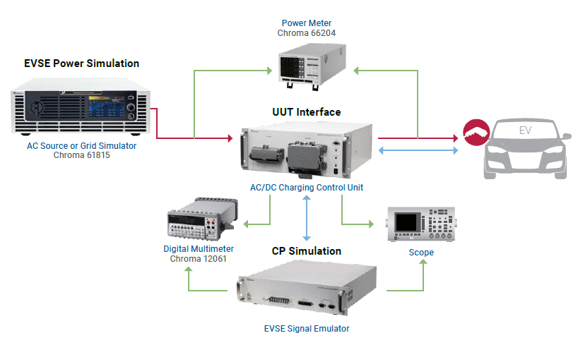
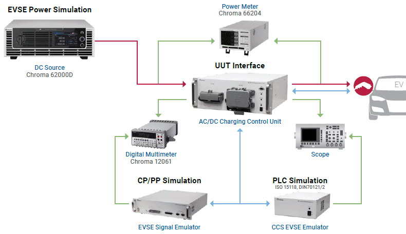
EV Power Components: EVSE Testing Solutions
[Tech Review] Prevent Li-ion Batteries from Catching Fire with Correct Jelly Roll Insulation Test
Addressing Fire and Explosion Risks in EVs and ESSs
The continuous increase in energy demand, as well as improved performance are simulating the rapid maturing of lithium-ion batteries in large energy applications such as electric vehicles (EV) and various renewable energy storage systems (ESS). However, the rapid increase in battery usage, energy density, and high-speed charging and discharging comes with a rise in fire and explosion incidents. Recent combustions of 3C products have instigated a widespread fear of using lithium batteries and news coverage of EVs that caught fire during or after charging has even raised people’s doubts about buying EVs. Recurrent ESS combustions in South Korea has caused the rapid expansion of ESSs around the globe to slow down.
Causes of Lithium-ion Fires: Metal Burrs and Particles
Most fire accidents of Li-ion batteries are initiated by severe inflammation and it is difficult to analyse the actual cause. Common reports contain the electrical control system errors or the lithium metal deposition compiling over a long time and growing into lithium dendrite, which cause internal short circuits in the battery. Although these are certainly possible factors, detailed analysis shows that they are difficult to establish in the bulk of battery accidents due to acute cluster chemical combustion. Test reports and battery cell manufacturers avoid the topic of how spontaneous internal short circuits are induced in Li-ion batteries, if not by lithium dendrite. Metal burrs or particles that puncture or exist in the separator may be a possible cause. The reason why existing manufacturing processes fail to identify this remains unclear. Although the defective rate is not high and the amount is considered acceptable, accidents that occur on the market, in the storage plant, or finished vehicle, or even impact the lives of people are highly newsworthy.
Dangers in Charging Li-ion Batteries
In addition, most fire accidents in Li-ion batteries occur while charging. The main reason is that the negative electrode materials used in Li-ion batteries could inflate, causing potential defective products that have not been short-circuited to become internal short circuits. Research has shown that this inflation will continue to expand repeated charge and discharge cycles, so that the danger will even extend to the user when using the battery. This means that although the battery may not have internally short-circuited during production when the separator is partially pierced by metal burrs or particles, there is a risk that such defects from a common production process cannot be effectively detected. The most prevalent problems in production inspection on battery cells are ① too low dry cell (jelly roll) insulation test voltage (<350V), and ② flashover that temporarily damages the separator and cannot be detected by general insulation testers.
Chroma ATE recommends including these two as standard test items during battery cell inspection:
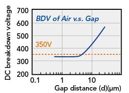
– Jelly roll insulation test voltage must be over (350V + α) peak value (Figure 1).
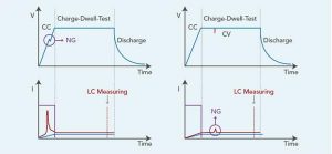
– Voltage/current flashover shall not occur during the insulation/withstand voltage test (Figure 2).( Concept referred to general electrical safety regulation.)
Chroma’s experts have drawn these conclusions from examining large numbers of analysis reports, research documents, and long-term experiments. Correct jelly roll insulation testing is a highly effective and low-cost method to prevent Li-ion batteries from catching fire.
Major international car battery manufacturers have recently adopted Chroma’s two unique technologies as well as the above two recommendations to ensure the safety and quality of their battery cells.
With well over 30 years of experience in testing and technology for power electronics, Chroma ATE continues to ride the wave. The test equipment manufacturer drives testing solutions for EV-related industries to ensure the safety, quality, and reliability of your products.
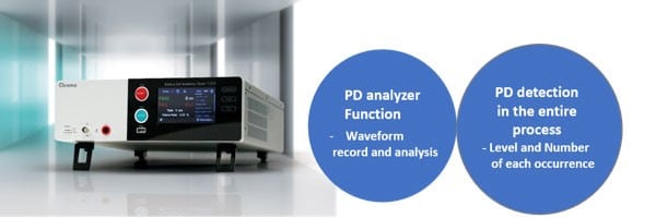
Chroma 11210 Battery Cell Insulation Tester is specifically designed for the detection of abnormal insulation of lithium-ion batteries (dry cells). The tester offers two unique technologies that other withstand voltage or insulation testers on the market do not have. Chroma 11210 not only monitors the entire process of testing for flashover due to abnormal partial discharge in the battery cell but also quantifies it in numbers and recordable waveforms. Moreover, after reaching the test voltage, the leakage current or insulation resistance will be measured and judged as abnormal during the test time like using WV/IR testers.
View all Chroma products available from MDL Technologies
Want further information, advice or a quote? Speak with our expert consultants about any of the Chroma products available on 01462 431981, or contact us here.
Advantages of measuring discontinuous disturbances with the PMM CA0010
Solving the pitfalls of single-run measurement permitted by CISPR 14-1 edition 7
New challenges in click analysis
The seventh edition of the CISPR 14-1 standard puts an accent on the technological progress of click analyzers, whose dynamic range needs to be wide enough to detect much more than the apparent lowest and highest quasi-peak readings at a time so they can complete the measurement in a single run.
Designed to make it faster and less costly to perform a complete standard-compliant click measurement, recent technology makes use of state-of-the-art Fast Fourier Transform (FFT) EMI receivers, which can cover all four of the required frequencies simultaneously.
Rather than needing four distinct receivers or four instances to complete a measurement, today’s FFT-based instruments do everything at once. Though this is clearly an advantage, they do have certain pitfalls:
– The reduced dynamic range, emphasized in FFT receivers and single-run systems, can lead to undermeasurement.
– As single-run systems consider only the amplitude of the disturbance but not its shape in time, they are susceptible to erroneous click analysis.
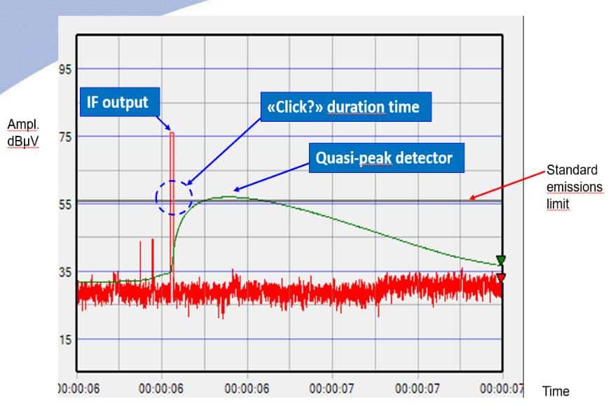
In Fig. 1, the red and green plotlines are simultaneous, gapless, real-time representations of the IF level and quasi-peak detector output with a resolution of 500 μs, as required by the standard. A very short pulse signal, for example a click disturbance lasting less than 1 ms, shows a high peak IF level and a modest quasi-peak detection. During the first run of the measurement process, at least 40 dB of instantaneous linear dynamic range is required to carry out this step correctly.
For the second run, the limit threshold could increase by as much as 44 dB depending on the click rate, according to the relaxed CISPR parameter:
44 dB for N < 0.2
or
20 LOG (30 / N) dB for 0.2 ≤ N < 30
In other words, a clean 84 dB of dynamic range is needed to complete a reliable measurement in a single run. As we can calculate with the formula 20 LOG (30 MHz / 9 kHz), which takes into account the 30 MHz total input bandwidth and the 9 kHz CISPR IF bandwidth, about 70 dB is irremediably lost by a standard 0 to 30 MHz receiver. Moreover, since the threshold level can be non-flat for the four frequencies required by the standard (depending on the equipment under test), a single attenuator for the entire band would have to be set for the highest limit to avoid saturation, thus wasting an additional 10 dB.
Benefits of the PMM CA0010 click analyzer
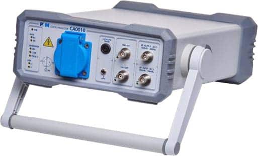
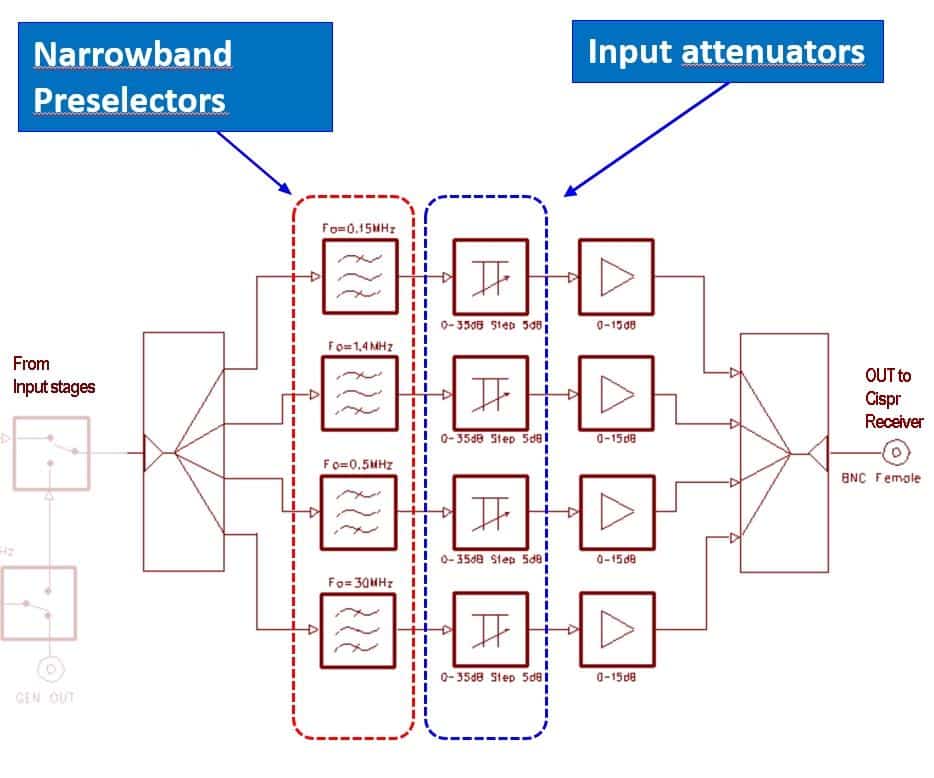
The PMM CA0010 (Fig. 2) is equipped with narrow preselection filters and independent attenuators for each single channel, as depicted in Fig. 3. These additional filters are tailored for CISPR 14 measurements; along with the specific attenuators, they are separate from and precede the filters of the ordinary preselector. This solution, combined with the high dynamic capability of the input circuits, makes it possible to manage signals of very different amplitudes as are typical of click disturbances.
The innovative design of the PMM CA0010, with its dedicated hardware, aims to overcome all of the pitfalls described above. Another advantage of this product is that while it measures clicks, it displays and records in real time a complete set of data: number, time, level, duration, etc. This can be done during development and/or debugging, so problems can be identified long before the production phase, saving considerable time and money.
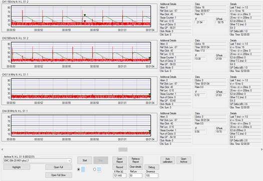
Reliable recording is also crucial for storing automated documentation of measurement results. Highly detailed data allows further investigation and comparisons that are impossible with basic summary tables. PMM CA0010 strip charts (examples in Fig. 1 and Fig. 4) let the user view signals over the entire test time to identify closely- and widely-spaced discontinuities. The output also shows the limits prescribed by the standard for the purpose of immediate comparison. The full set of data is stored in the PC and can be reloaded at any time for further investigation.
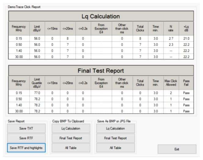
The final test report can be exported in easy-to-use TXT format, or as a more flexible and detailed PDF or RTF file.
Reports can be recalled whenever needed and in any of these common formats. An example is shown in Fig. 5.
Conclusion
The FFT technique and the powerful computing boards that are now widely available enable the simultaneous click measurement of all required frequencies. However, this numerical approach alone cannot overcome all the physical limitations associated with the measurement of discontinuous disturbances.
For example, the receiver must be able to detect very low signals while not getting saturated with very high disturbances. This makes channel-individual input filters and attenuators indispensable. Narrowband frequency preselection at the RF input is necessary for ensuring CISPR compliance in a single run.
The PMM CA0010 is not only equipped with this additional hardware but comes with an internal 16 A LISN, internal reference and calibration generator. Click analysis and click generation software are also provided.
View all PMM products available from MDL Technologies
Want further information, advice or a quote? Speak with our expert consultants about any of the PMM products available on 01462 431981, or contact us here.
Chroma’s HP Multi-coupler Charging Tests Drive Fast EV Charging

How EMScanner Diagnoses Board-Level EMC Design Issues
If you are in a PCB Design Team, including Designers and Verification Engineers, and you face EMC challenges? Then this Application Note will assist you how the EMScanner diagnose board-level EMC Design Issues.
The EMScanner provides board-level design teams with world-leading fast magnetic very-near-field data to help diagnose EMC design challenges. The instrument captures and displays visual images of spectral and real-time spatial scan results in seconds.
Want to know more? Please Download the Application Note:

Want further information, advice or a quote? Speak with our expert consultants about any of the YIC Technologies products available on 01462 431981, or contact us here.
Chroma 62000D Series – Programmable Bidirectional DC Power Supplies
Chroma 62000D: Bidirectional Battery Testing
Increasing developments in renewable energies along with the rapid growth of electric vehicles are motivating the commercialization of distributed energy sources in micro grids. The same goes for the bidirectional design of power conversion devices. These devices are motivating battery applications to achieve higher efficiencies, higher voltage conversion, and higher power densities. With that said, design and test engineers are looking to replicate these characteristics from battery simulators with bidirectional DC power capabilities for their product development.
The Chroma 62000D not only provides source and load modes but offers a bidirectional switch-mode that enables two-quadrant operation providing both DC power and regenerative DC loading. The absorbed energy feeds back to the grid with an efficiency of up to 93%. The regenerative load modes include constant current, constant voltage, and constant power and can simulate the battery for testing battery connected charging devices. Where conventional methods required both DC power supply and regenerative DC load, one single Chroma 62000D can fulfil both charging and discharging tests in one unit.
Take a closer look in this official video:
Key Features
– Voltage rating: 0 ~ 100V/600V/1200V/1800V
– Current rating: 0 ~ 540A
– Power Rating: 6kW/12kW/18kW
– Two quadrant operation: source and load functions
– High power density: 18kW in 3U
– Easy master/slave parallel &series operation up to 180kW
– Wide range of voltage & current combinations in constant power
– Auto sequencing programming
– Standard USB/LAN/APG interfaces, optional CAN/GPIB interfaces
Intuitive touch screen interface.
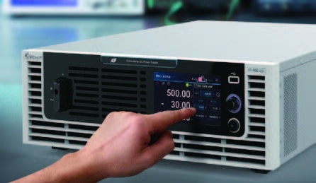
The Chroma 62000D has a next generation human-machine control interface with an intuitive and user-friendly touch screen. Operation of the apparatus is as easy as using a smartphone, with its intelligent and convenient user interface; through icons on the touch screen, the user can complete any voltage/current settings and measurements, program sequence control settings, preview output waveforms, etc.
Want further information, advice or a quote? Speak with our expert consultants about any of the Chroma products available on 01462 431981, or contact us here.